
 English
 中文简体
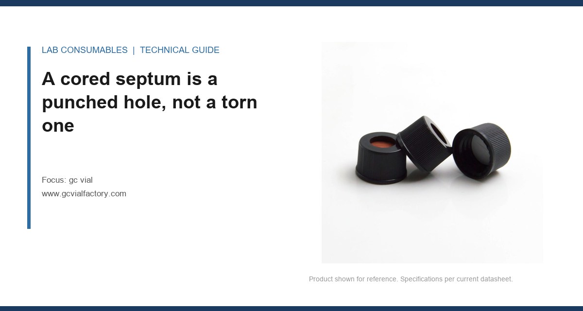
A 40-sample sequence ran overnight. By injection 17, the peak for methyl parathion had split into a doublet, and by injection 23 the syringe plunger started sticking. The autosampler kept going, but the data was unusable. When I pulled the inlet liner, the glass wool at the bottom held a crescent-shaped sliver of blue PTFE and a few angular chips of silicone. That is gc vial coring, fragments and needle damage diagnosis in its most direct form: the needle punched a plug out of the septum instead of spreading it, and the plug rode down into the inlet.
Coring is a mechanical cut. The needle tip acts like a hollow punch. If the tip geometry is a flat bevel with a sharp inner edge, the downward stroke shears a circular or crescent plug from the septum material. That plug stays inside the needle bore or drops into the inlet. A torn septum, by contrast, shows radial splits from repeated off-center entry. The two failure modes look different under magnification, and they have different causes. If you treat a cored septum as a wear problem, you will replace the septum and keep damaging needles on every new vial.
The plug itself is the diagnostic. Under a 10x loupe, a cored PTFE/silicone septum plug has a clean outer circumference and a thickness that matches the septum layer it came from. A torn fragment is irregular, feathered at the edge, and often folded. The distinction matters because a clean plug means the needle tip cut the material on entry. A torn fragment means the needle was already bent or burred and ripped the septum on the way through.
Needle tip geometry that actually cuts a plug
Most GC autosampler syringes use a 22s or 23s gauge needle with a bevel tip. The bevel angle and the sharpness of the inner bore edge control whether the tip spreads the septum or cuts it. A standard 22s bevel is ground at 12 to 17 degrees. The inner edge of the bore, where the bevel meets the lumen, is the cutting edge. If that edge has a burr from grinding or from hitting the bottom of a vial, it becomes a punch. The burr catches the septum surface and shears a plug on the first 1 to 2 mm of travel.
I have measured this. A new 23s needle with a clean bevel will puncture a standard 11 mm PTFE/silicone septum 50 times before the puncture force rises by more than 20 percent. A needle with a burr on the inner bore edge will core the same septum on puncture 1. The difference is not septum quality. It is the needle. Replacing the septum without inspecting the needle guarantees the next septum fails the same way.
The second geometry factor is the needle OD relative to the septum thickness and the guide hole in the cap. A 0.63 mm OD needle (23s gauge) entering a 0.8 mm guide hole has 0.17 mm of lateral clearance. That is enough for the needle to enter slightly off-axis if the autosampler arm has any play. An off-axis entry concentrates force on one edge of the bevel, which increases the chance of cutting. A 0.47 mm OD needle (26s gauge) in the same guide hole has more clearance and wanders more. The tighter the guide, the more perpendicular the entry, and the less likely the tip is to catch and shear.
What the debris under a loupe tells you before you touch the inlet
Before you pull the inlet apart, collect the debris. Place a clean white weigh paper under the septum cap, invert the vial, and tap gently. Then examine the cap underside and the septum surface. Use a 10x to 20x loupe or a stereomicroscope. You are looking for three things: the shape of any fragments, the color of the fragments, and the location of the hole in the septum.
A crescent-shaped blue or white PTFE sliver means the needle cut the top PTFE layer. A black or gray angular chip means the needle cut the silicone core. A mixed fragment with PTFE on one face and silicone on the other means the needle cut through both layers in one stroke. That is a sharp inner bore edge doing clean work. A clean hole with no fragments means the plug is still inside the needle or already in the inlet liner.
The hole location matters more than most people think. A hole exactly in the center of the septum, within 0.2 mm of the cap center, points to a needle geometry problem. The autosampler is hitting the target, but the tip is cutting. A hole 0.5 mm or more off-center points to an alignment problem in the autosampler arm or a loose guide. The off-center entry drags the bevel across the septum surface, which tears rather than punches. You fix those two cases differently.
The guide hole and cap crimp dimensions that force a core
The cap on a 9 mm crimp-top gc vial has a guide hole in the aluminum or polypropylene shell. That hole is not a passive opening. Its diameter, its concentricity with the septum, and the crimp force that holds the septum all influence whether the needle cores the septum on entry.
I have seen caps where the guide hole was punched 0.3 mm off-center relative to the septum. The needle enters through the hole, hits the septum at an angle, and the bevel edge catches the PTFE face. The result is a crescent plug on the first injection. The fix is not a softer septum. It is a cap with a concentric guide hole and a septum that sits flat in the cap before crimping.
Crimp force is the other variable. An 11 mm aluminum cap crimped to a final height of 3.0 to 3.2 mm applies enough compression to hold the septum but not so much that the septum becomes rigid. If the crimp is too tight, the septum is compressed into a hard puck. The needle then has to punch through a denser material, and the inner bore edge is more likely to cut a plug. If the crimp is too loose, the septum shifts during puncture and the needle tears it. The sweet spot for a standard 1.3 mm thick PTFE/silicone septum is a crimp height that leaves the septum slightly domed, not flat and not bulging.
Septum material and hardness: two numbers that predict coring
Septum hardness is reported on the Shore A scale. A typical PTFE/silicone GC septum runs 45 to 55 Shore A. A butyl/PTFE septum runs 50 to 60 Shore A. A harder septum resists coring because the needle tip has to work harder to shear a plug, but a too-hard septum increases puncture force and can bend the needle. A too-soft septum, below 40 Shore A, is easy to puncture but tears more readily and leaves fragments behind.
The PTFE facing layer thickness also matters. A 0.25 mm PTFE face over a silicone core is the standard for 9 mm caps. A thicker PTFE face, 0.5 mm or more, resists coring better because the PTFE is slippery and the needle slides through rather than cutting. But a thicker PTFE face reseals less effectively after multiple punctures. For a 100-injection sequence, a 0.25 mm PTFE face is the practical minimum. For a 200-injection sequence, you need a 0.5 mm face or a pre-slit septum.
Pre-slit septa eliminate coring by removing the material the needle would cut. The slit is a controlled cut made at the factory. The needle follows the slit instead of punching through intact material. The trade-off is that a pre-slit septum has a lower reseal limit. After 50 to 100 injections, the slit can open up and cause seal loss. That is a separate failure mode, one that belongs to the seal loss article, not this one.
Autosampler alignment and the puncture sequence
The autosampler drives the needle down at a set speed. A typical Agilent 7693A or 7650 autosampler lowers the syringe at 20 to 50 mm/s. The needle hits the septum and decelerates. If the needle is perfectly perpendicular and the tip is clean, the septum deforms elastically and the needle passes through. If the needle is off-axis by even 0.5 degrees, the bevel edge engages the septum at an angle and starts a cut.
The guide hole in the cap is supposed to correct for small misalignments. But if the guide hole is too large relative to the needle OD, it cannot correct anything. A guide hole of 0.9 mm with a 0.63 mm needle leaves 0.27 mm of lateral play. That is enough to let the needle enter at a shallow angle. A guide hole of 0.7 mm with the same needle leaves 0.07 mm of play. The tighter guide forces perpendicular entry. When I specify caps for a lab that runs 200 injections per vial, I require a guide hole no more than 0.1 mm larger than the needle OD.
The puncture count per septum is also a mechanical limit. A standard 11 mm PTFE/silicone septum with a 0.25 mm PTFE face is rated for 50 to 100 punctures with a 23s needle. Beyond that, the septum loses its ability to reseal and the puncture force rises. The rising force increases the chance that the needle tip will catch and core on the next puncture. If you are running 150 injections from one vial, you are past the rated limit and you should expect debris.
Field case one: the crescent that matched the needle burr
A contract lab running EPA Method 8270 for semivolatiles called me after three consecutive sequences failed with split peaks. The method uses a 5 µL syringe with a 23s needle and a 9 mm crimp-top vial with a PTFE/silicone septum. The analyst had replaced the septum twice and the inlet liner once. The problem persisted.
I asked for the used septum and the syringe. Under a 20x loupe, the septum showed a crescent-shaped hole at the 11 o’clock position, 0.4 mm from center. The PTFE face around the hole was cleanly cut. The silicone underneath was not torn. The syringe needle, viewed under the same loupe, showed a small burr on the inner bore edge at the tip. The burr was not visible to the naked eye.
The fix was to replace the syringe. The new needle, inspected under the loupe before use, had a clean bevel and no burr. The next sequence ran 40 injections with no split peaks and no debris in the liner. The septum was the victim, not the cause. Replacing it without checking the needle had wasted two septa and one liner.
Field case two: the off-center guide hole that cored every first injection
A food testing lab running pesticide residues on a GC-MS with a 7693A autosampler reported debris in the inlet after every first injection from a new vial. The debris was a small blue PTFE sliver. The lab was using a new lot of 9 mm crimp caps from a different supplier. The septum was the same part number they had used for years.
I measured the guide hole in 20 caps from the new lot. The hole was punched 0.25 to 0.35 mm off-center in 12 of the 20 caps. The septum sat flat, but the needle entered through the off-center hole and hit the septum at an angle. The bevel edge caught the PTFE face and cut a sliver on the first puncture. The fix was to return the lot and go back to the previous cap supplier. The septum was fine. The cap was the problem.
This is why you cannot diagnose coring by looking only at the septum. The cap, the needle, the autosampler alignment, and the septum all contribute. The debris tells you which one failed.
A decision checklist for coring and needle damage
When you see debris in the inlet or a sticking syringe, work through this list in order. Each step has a concrete measurement or observation. Do not skip to replacing the septum.
- Check the syringe needle under 10x to 20x magnification. Look for a burr on the inner bore edge, a bent tip, or a flat bevel with a sharp inner edge. Replace the syringe if any of these are present.
- Measure the hole location in the septum. A hole more than 0.3 mm from center points to cap guide hole misalignment or autosampler arm play. A centered hole points to needle tip geometry.
- Examine the debris shape. A clean crescent or circular plug means the needle cut the septum. An irregular, feathered fragment means the needle tore it, usually due to a bent tip or off-axis entry.
- Check the guide hole diameter and concentricity. The guide hole should be no more than 0.1 mm larger than the needle OD and centered within 0.1 mm of the cap center.
- Measure the crimp height. For an 11 mm aluminum cap on a 9 mm vial, the final crimp height should be 3.0 to 3.2 mm. Below 2.8 mm the septum is over-compressed. Above 3.4 mm the cap is loose.
- Verify the puncture count. If the vial has seen more than 100 punctures with a 23s needle, the septum is past its rated limit. Replace the vial or switch to a pre-slit septum for longer sequences.
- Check the needle OD against the guide hole. A 0.63 mm needle in a 0.9 mm guide hole has too much lateral play. Use a cap with a tighter guide or a larger needle.
Septum and cap selection parameters that reduce coring
If you are specifying vials and caps for a method that runs long sequences or uses a fast autosampler, these are the numbers I use. For a standard 9 mm crimp-top sample vial, a 1.3 mm thick PTFE/silicone septum with a 0.25 mm PTFE face and 45 to 55 Shore A hardness is the baseline. The cap guide hole should be 0.7 mm for a 0.63 mm needle, or 0.5 mm for a 0.47 mm needle. The crimp height should be 3.0 to 3.2 mm.
For a 200-injection sequence, move to a 0.5 mm PTFE face or a pre-slit septum. The pre-slit septum eliminates coring by removing the material the needle would cut, but the reseal limit drops to 50 to 100 injections. If the method requires 200 injections from one vial, a pre-slit septum is the wrong choice. Use a thicker PTFE face instead.
The needle itself is a consumable. A 23s needle with a clean bevel is good for 50 to 100 punctures before the inner bore edge starts to dull. After that, the puncture force rises and the risk of coring increases. Replace the syringe at the same interval as the septum, not when it visibly bends. A needle that looks fine under the naked eye can still have a burr that cores the next septum.
For methods that use a hplc autosampler vial with a snap cap or a screw cap, the same principles apply. The guide hole dimensions change, but the needle tip geometry and the septum hardness are the same variables. A screw cap with a 0.8 mm guide hole and a 0.63 mm needle is fine. A snap cap with a loose septum is not.
When I order septa in bulk, I specify the hardness range and the PTFE face thickness on the purchase order. I do not accept a certificate that only says “PTFE/silicone.” That is not enough. The reagent bottle and vial suppliers that give me real numbers are the ones I keep.
What the inlet liner shows after a coring event
The inlet liner is the second place to look, after the septum and the syringe. A cored plug that falls into the liner usually lands on the glass wool or the bottom of the liner. It does not vaporize. PTFE decomposes at temperatures above 260 °C, but a plug sitting in the liner at a 250 °C inlet may take many injections to break down. Silicone fragments char and leave a white residue. The debris causes peak tailing, split peaks, and ghost peaks because it adsorbs analytes or disrupts the vaporization zone.
If you see a blue PTFE sliver in the liner, replace the liner and the septum. If you see a black charred fragment, the silicone core was cored and the plug sat in the hot zone too long. In both cases, inspect the needle before running the next sequence. Replacing the liner without replacing the needle just moves the problem to the next vial.
The Agilent chromatography consumables documentation for inlet maintenance specifies liner replacement intervals and the symptoms of a contaminated liner. The Thermo Fisher chromatography resources cover septum selection and autosampler maintenance. Both are worth checking when you set up a preventive maintenance schedule.
When the coring is not the septum, the cap, or the needle
There is one more cause that gets missed: the vial mouth itself. A 9 mm crimp-top vial has a mouth ID of 6.0 mm and a mouth OD of 9.0 mm. If the vial mouth has a chip or a burr on the rim, the septum does not sit flat. The cap crimps down on an uneven surface, and the septum is compressed unevenly. The needle then enters through a region of higher compression, and the inner bore edge cuts a plug.
I have seen this with a lot of vials that were dropped during shipping. The rims had small chips, invisible without a loupe, but enough to distort the septum compression. The fix was to inspect the vial rims under magnification and discard any with chips. A gc vial with a damaged rim is not a precision component anymore.
The U.S. EPA SW-846 test methods for waste and materials include specific requirements for sample containers and septa. Method 8260 for volatile organics, for example, requires septa that do not leach or core under the specified injection conditions. If you are running EPA methods, the septum specification is part of the method compliance, not a preference.
The Restek technical resources have good chromatograms showing the effect of septum debris on peak shape. A split peak from a cored septum looks different from a split peak from column overload. The septum debris causes a variable split that changes from injection to injection. Column overload causes a consistent split. If the split peak is intermittent, look at the septum and the needle first.
The decision rule
When you see debris in the inlet or a sticking syringe, do not replace the septum and hope. Inspect the syringe needle under 10x to 20x magnification first. If the inner bore edge has a burr, replace the syringe. Then measure the hole location in the septum. A centered hole points to needle geometry. An off-center hole points to the cap guide or autosampler alignment. Then check the guide hole diameter and the crimp height. If the guide hole is more than 0.1 mm larger than the needle OD, or the crimp height is below 2.8 mm, the cap is the problem. Only after ruling out the needle, the cap, and the alignment do you replace the septum. That order saves time and prevents the same failure on the next vial.
References & further reading
Related resources from our lab consumables network:
- Gc Vial at gcvialfactory.com
- Reagent Bottle at reagentbottleforsale.com
- Hplc Autosampler Vial at hplcautosamplervials.com
- Sample Vial at samplevialprice.com
External references and standards: